Ride Animation Rig Test
During the Spring of 2020, I was an intern on the Ride and Show Performance team at Universal Creative. That team was responsible for ride and show programming, with a major focus on ride motion animation. My role, as part of the team, was primarily to develop tools and scripts to assist in the ride animation process and occasionally participate in the authoring of attraction content. During my time there, I did a lot of work that is unable to be discussed in depth due to non-disclosure agreements, including some direct work on upcoming attractions, but the process that most interested me while I was there was the animation of ride motion.
We'd take digital, 3D representations of our ride vehicles, and with the automation provided by some very well-put-together scripts by some of the more engineers on the team, we'd be able to directly animate the motion we'd desire by controlling the various degrees of freedom. We could validate those values in real-time against the mechanical limits of the system, then use another script to export the ride motion into precise mechanical instructions to be installed onto a real ride vehicle for testing.
It was really cool.
My internship was effectively cut short due to the start of the COVID-19 pandemic - everyone was sent to work from home about halfway through (me included), and while I was still doing the cool software/digital work, the practical/physical aspect that I really enjoyed vanished. It was still a great experience, but was unfortunate in timing.
A few months after my internship was over, I decided to start a little experiment on my own. Could I build the rig for (and animate) a whole make-believe ride vehicle and system from scratch in a totally different software suite?
That's where this project comes in.
Software
The software we used at work was mostly Autodesk 3DStudio Max, with its built-in scripting language driving most of our automation. It was, frankly, clunky and dated. It took minutes to load on SSDs, would chug with any sizable amount of vertices, and had a UX experience held back by decades of backwards compatibility.
On top of that, it's pricey.
With some previous experience in the tool, I decided to use Blender3D. I hadn't played with it much since the 2.8 release, which totally rennovated the UX of the software, and I hadn't ever tried writing python code for the platform. But it was something that seemed quite useful to me. Writing directly in python allows for the use of the existing python platform, alongside the benefits of a modern interpreted language. Blender, too, was growing in leaps and bounds when I started playing with it again, putting it on par - or even better - than the software we'd been using.
And it's free. Forever.
Getting Started
I started this project with a few goals for the ride vehicle: make it unique, make it slightly unfeasible for practical construction, be high-capacity, and have some creatively-different element to the motion.
The solution for the last goal was found pretty quickly - most dark ride RVs have very limited motion along the roll axis, with that axis even being positioned below or close to the feet of the guests. So, I imagined guests sitting on the inside of a horizontal barrel, that can roll along infinitely, controlled by some electronic drive motor.
Definitely unfeasible for practical construction. So that goal is done, too.
The next challenge is implementing the other degrees of freedom.
Heave/pitch is relatively simple. A pair of linear actuators at the front and back of the barrel allow the vehicle to pitch forward/back, or heave up and down.
Yaw is a little more complicated. I imagined the linear actuators being joined to the base of the transport at one point on the front and back. Therefore, sliding that point left/right would allow the barrel to yaw slightly, as long as the opposite point was moving in the opposite direction.
This would also allow for strafing of the vehicle, dodging left and right. But I'd imagine the physical forces associated with that would be... not safe.
I drew up these initial plans below.

I am... not a mechanical engineer.
Creation in Blender
My first goal was making things at the appropriate scale. In Blender, every unit is equal to one meter. With that in mind, I created this rough model of a sitting human, with 95th percentile measurements I found online.

From there, I built the very first iteration of the ride vehicle around the human. Four rows for four people, at the bottom of a sideways barrel, following the plans I'd laid out before, and...

No good.
The rig was all broken already, let alone the quality of the model itself. I ended up scrapping the entire model, and starting from scratch (though keeping the humans).

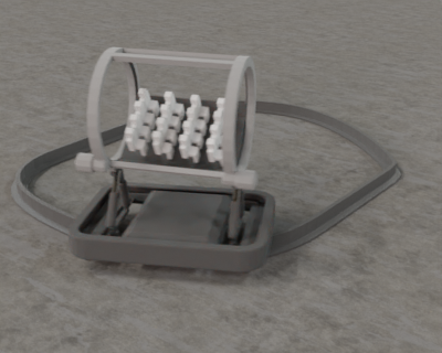
I finally figured out what I needed to do, how to do it, and actually put it together properly. Even added little wheels on the transport for fun.
Rigging the Vehicle
The biggest convenience we had with the rigs we'd put together at universal was the use of a single "empty" object that held all the animation programming for the entire vehicle. While sometimes there'd be two, on more complicated rigs, the typical plan was to have a single object and then animate that to drive the vehicle. Very easy to use, very clean, and great for organization. So, I tried to do that here.
The ride rig has a single root object (vehicle origin), from which everything is a child. An immediate child of that is the "Program Motion" object, which exposes all the axes of motion for the motion platform abord the RV.
For this rig, the axes are somewhat separated on what they impact directly. The roll axis, for example, (x, in blender) only affects the inner guest platform of the barrel. So, that object is driven by the roll axis value. Pitch, Yaw, and Heave (rot y, rot z, loc z) were driven by the outer barrel (rings), so that object is driven on those axes by those values.
Once the main motion components of the rig are set up, the rest of the work is making the child "puppet" elements react and move with the main motion components. In my case, that's the pair of actuators at the front and back of the RV, and their sliding mount on the transport base. That was... a headache. But I finally got it working with a few empty objects and plenty of use of blender "Constraints."
After that was all done, I threw a simple little test animation together and rendered a little playblast.
Building a little ride vehicle on its own is fun, but the real beauty of ride vehicles comes from them moving on a track, in a fleet. That was the next challenge.
As it turns out, I really should have built that rig around that from the start. It took quite a bit of fiddling with the rig to get it behaving.
Getting On Track
The initial, naive approach is to pin the ride vehicle to the ride track (represented by a bezier curve) and have it face the direction of travel. Blender makes this easy - the "Follow Path" object constraint does this exact thing. Pinning the object root to this constraint means that the ride vehicle now follows that curve with an animation parameter that is part of the curve object, and turns with the ride path.
That solution poses two problems:
- Only one velocity is shared betwen all vehicles on the path.
All objects that have the "follow path" constraint follow the same position value animated on the curve object itself. This would be valid for something like an omnimover attraction, where all vehicles can only have the same speed, but for nothing more advanced.
- The vehicle has infinite turning speed on the track, and is clamped to a single, infinitessimally small point
In real life, most ride vehicles pinch a drive rail at two points - one leading the center of the vehicle and one trailing the center of the vehicle. This means that the vehicle turns around corners in the track in a unique - but real - fashion. This isn't done with this solution.
In addition, this method has the infinite turning speed. That's not realistic, and now how vehicles work. Therefore, this is a bad solution.
What do we do?
I found it best to start by rigging the pair of clamps - two empty objects that sit at the approximate real-life location on the vehicle. The "origin" of the vehicle has a "Copy Location" constraint on the leading clamp, and another "Copy Location" constraint on the trailing clamp, set to 50%. This places the vehicle right in the middle of the pair of clamps. On top of this, you can have the trailing clamp "look at" the leading clamp, and "Copy Rotation" along the vertical axis onto the vehicle. Therefore, the ride vehicle now follows the pair of clamps.
The solution for the "Follow Path" constraint is to instead use the fittingly named "Clamp To" constraint. In this case, the x/y/z position of the object is mapped to a position on the bezier curve. Exactly what we want, as the value can be driven independently for each instance of the vehicle on the track.
With a little bit of driver magic to position the clamp's position based on a custom variable on the "Program Motion" object, we've got our fully-rigged ride vehicle.
With a little bit of polish, we have this:
Of course, a lone ride vehicle isn't quite enough to develop a whole attraction. You'd need a pair of them, at the very least, to see sightlines of vehicles ahead and behind. But how to automate that....